Case Study FFS – Pressure vessel with a crack along the longitudinal seam
Standard procedure
The API/ASME FFS standard procedure defines 3 evaluation levels:
-
Level 1 this is the simplest, so-called basic evaluation procedure, which can be performed by an experienced inspector or plant engineer.
- simple manual calculations can also be performed during the process
- necessarily the most conservative valuation level (sometimes Level 2, 3 suits, but Level 1 not)
- In some cases Level 1 not allowed (e.g. seismic load, wind load, etc)
- In case of Level 1 the procedures prescribed in the FFS must be followed exactly, there is no room for independent or individual interpretation
-
Level 2: a more complex assessment procedure than Level 1, which can be carried out by an engineer trained in FFS. Most Level 2 calculations are done on predefined worksheets.
- the course and form of the calculations performed during the process are predefined according to FFS
- During the application of Level 2, greater engineering leeway is allowed in terms of technical decisions
- the engineer performing the evaluation must be familiar with FFS procedures
-
Level 3: this is the highest level of assessment that can be performed by a highly trained and experienced expert engineer. This level of FFS may include computer simulations (CAE, CFD, NVH) for the required stress and other engineering analyzes.
- during the Level 3 process, the FFS standard prescribes some design concepts, leaving the detailed development of the evaluation to the expert engineer
- since every technical situation is different, complex engineering procedures and calculations are difficult to organize into a system of successive practical steps, therefore the responsibility of the expert engineer is greater
- Level 3 evaluation is the most expensive procedure, but if a complex engineering analysis results in major failures and unplanned downtime being avoided, then it was probably a good investment
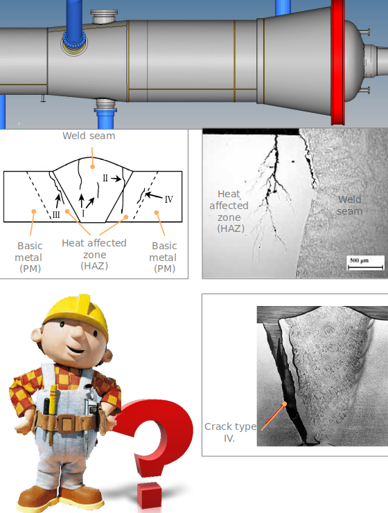
Definition of case study
INSPECTION:
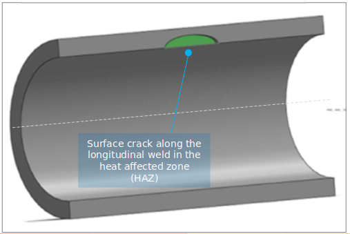
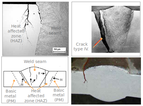
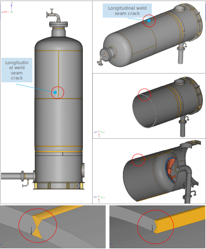
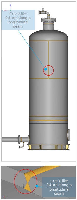
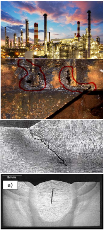
As a result of a periodic inspection, a crack along the longitudinal seam on the inner side of the vessel


TASK:
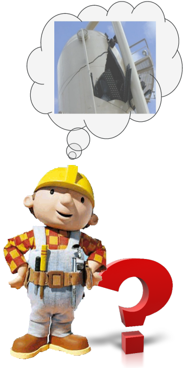
With the help of a standard FFS procedure (API 579/ASME, PD7910, FITNET) it is necessary to decide whether the equipment is suitable for safe further operation with a crack-like failure detected by a non-destructive test along the inner side of the longitudinal seam or not.

The API/ASME FFS standard procedure defines 3 evaluation levels::
- LEVEL 1: this is the simplest, so-called basic evaluation procedure, which can be performed by an experienced inspector or plant engineer.
LEVEL 2
: a more complex assessment procedure than Level 1, which can be carried out by an engineer trained in FFS. Most Level 2 calculations are done on predefined worksheets.LEVEL 3
: this is the highest level of assessment that can be performed by a highly trained and experienced expert engineer. This level of FFS may include computer simulations (CAE, CFD, NVH) for the required stress and other engineering analyzes.
ASSESSMENT STEPS:
1. Finding the cause of the failure
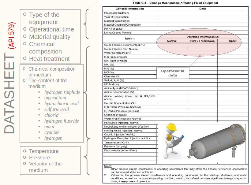
DATASHEET
revealing the failure mechanism- Malfunctions acquired before normal operation
- Malfunctions occurring during normal operation
2. Data needs (determination of technical data and mechanical characteristics)
DATASHEET
for the evaluation of crack-like failures- The original
design data
of the equipment - Equipment
maintenance
andoperating data
- Equipment
load
andstress distribution
Material properties
of the equipment (Rp02 ; Rm ; KIC )- Characteristics of crack-like
failure
3. API 579/ASME assessment methods
- 1. evaluation level (Level 1) : the simplest evaluation procedure can be performed by an experienced inspector or plant engineer
- 2. evaluation level (Level 2) : complex evaluation procedure, can be performed by an engineer trained in
FFS
- 3. evaluation level (Level 3) : can be performed by a highly qualified and experienced expert engineer at the highest evaluation level

Exploration of the cause of failure
Malfunctions discovered during the inspection of the equipment during operation may result from material or manufacturing defects and/or defects induced during operation:
Malfunctions acquired before normal operation of the equipment
- Material defects
- Defects related to the welding process (porosity, welding cracks, filling defects, etc.)
- Defects related to machining (root grinding, grinding cracks, dents, cuts, etc.)
- PWHT-related defects (PWHT cracks, embrittlement, etc.)
- Incorrect choice of material
- Malfunctions occurring during normal operation of the equipment
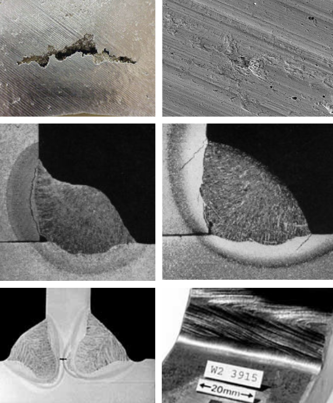
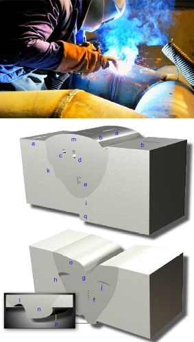
a – longitudinal crack
b – transverse crack
c – porosity
d – perforation
e – local porosity
f – linear porosity
g – shrinkage cavity
h – slag inclusion
i – imperfect filling
b – transverse crack
c – porosity
d – perforation
e – local porosity
f – linear porosity
g – shrinkage cavity
h – slag inclusion
i – imperfect filling
j – internal scare failure
k – side scare failure
l – root incision
m – seam height
n – seam filling
o – filling ditch
p – overlap
q – alignment error
k – side scare failure
l – root incision
m – seam height
n – seam filling
o – filling ditch
p – overlap
q – alignment error
Malfunctions discovered during the inspection of the equipment during operation may result from material or manufacturing defects and/or defects induced during operation:
- Malfunctions acquired before normal operation of the equipment
Malfunctions occurring during normal operation of the equipment
- Comprehensive and local material shortages due to corrosion and/or other erosion causes
- Cracks reaching the surface
- Cracks in material
- Material-induced micro-cracks (hydrogen disease, creep)
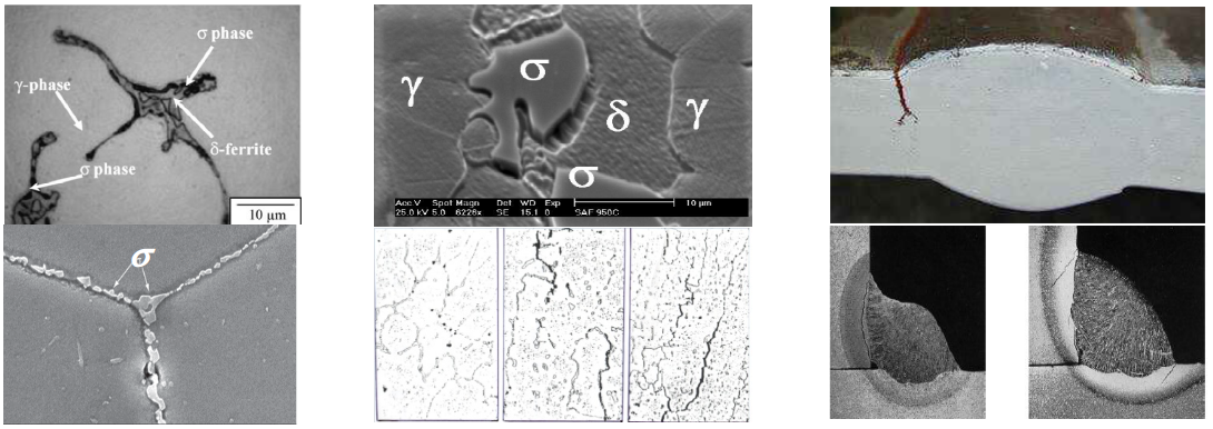
- Metallurgical changes of the material
- Embrittlement, granulation, and precipitation of graphite in carbon steels
- Ferritic and austenitic steels cause embrittlement. s-phase precipitates
- The embrittlement of ferritic and duplex stainless steels above 475°C
- 2.25Cr-1Mo steels experience embrittlement
Data need
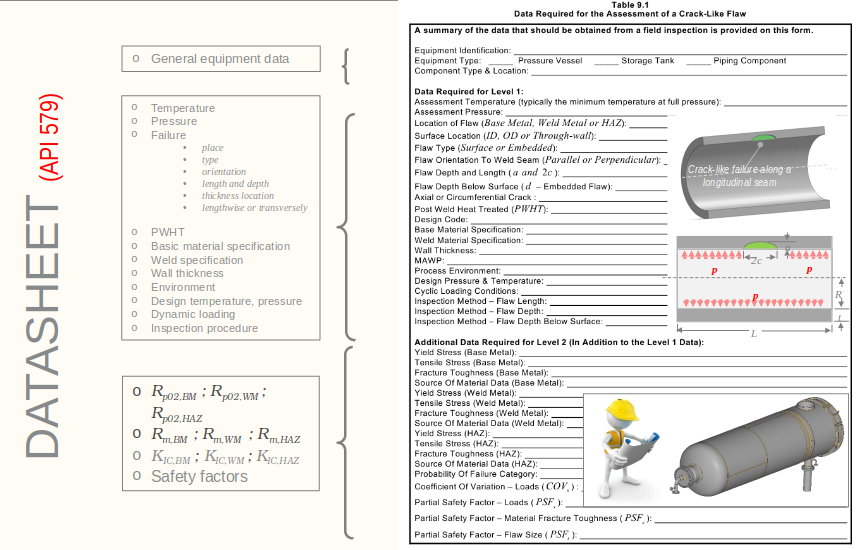
DATA NEED (DATA SHEET for the evaluation of crack-like failures):
DATA NEED:
The original design data of the equipment
- Important design dimensions of equipment (diameter, wall thickness, etc.)
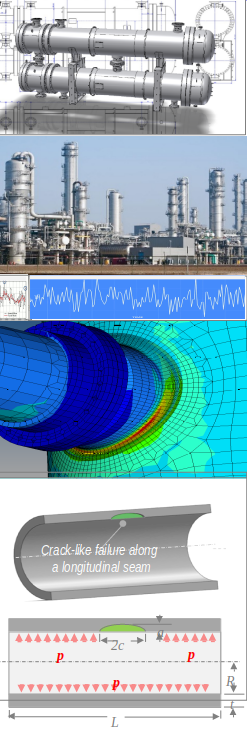
- Modeling (CAD/CAE) and calculation (stress, stress-intensity, etc.) data
- Dimensions, thicknesses, connections of stubs, covers, pipes, etc.
Equipment maintenance and operating data
- The most likely mechanism of failure
- The crack is growing or not
- Estimation of crack shape and dimensions
- Possible repair or remedial measures
Equipment load and voltage distribution
- Determination of relevant load cases (pressure, temperature, other mechanical loads, etc.)
- Calculation of stresses (based on analytical formulas STANDARD, numerical method - FEA)
- Classification of stress components (primary, secondary, permanent)
Properties of the material of the equipment (Rp02 ; Rm ; KIC)
- Mechanical and thermal constants (E, n, a, etc.)
- Yield strength and tensile strength values (Rp02 ; Rm ; real s-e curve - Ramberg-Osgood)
- Stress intensity values (KIC)
- Crack growth model (model+constants for determining remaining life)
Characteristics of crack-like failure
- Determining the length of the crack
- Determining the depth of the crack
- Characterization of branching cracks
- Characterization of multiple cracks
Inspection techniques
- Selection of a suitable NDE method
- in terms of crack location (surface, closed)
- in terms of correct determination of length, depth, orientation (angle) and position

Evaluation modes API 579/ASME
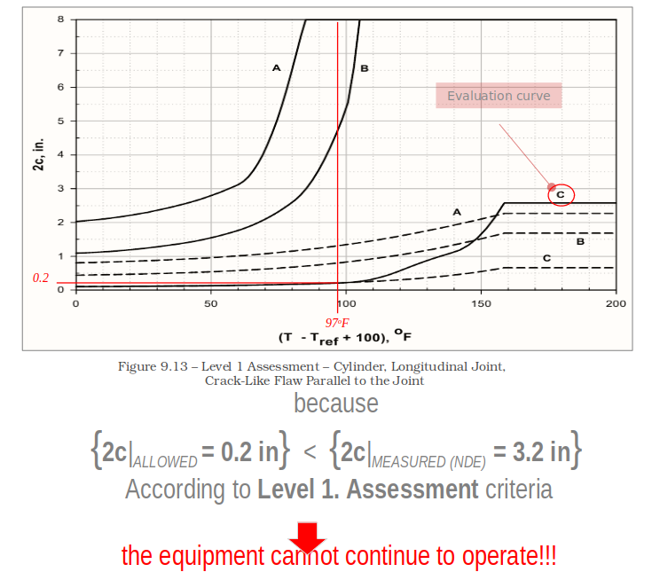
API 579/ASME EVALUATION MODES (Level 1. Assessment):
Step 1
- Loading of the equipment
- Equipment operating temperature
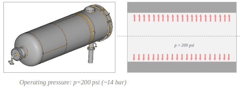
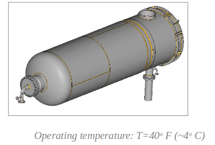
Step 2
- Dimensions of crack-like failure (length, depth, location)
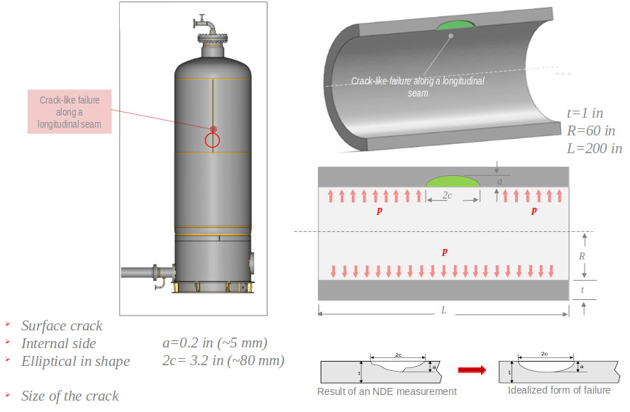
Step 3
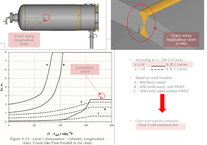
- Selection of API Chart based on tank type and crack location
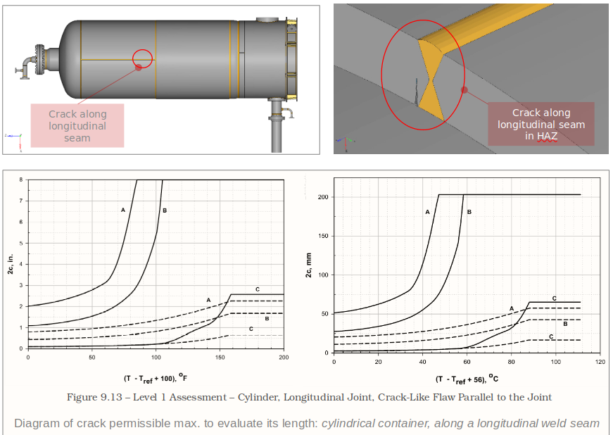
Step 4
- Determination of the permissible crack length curve
Step 5
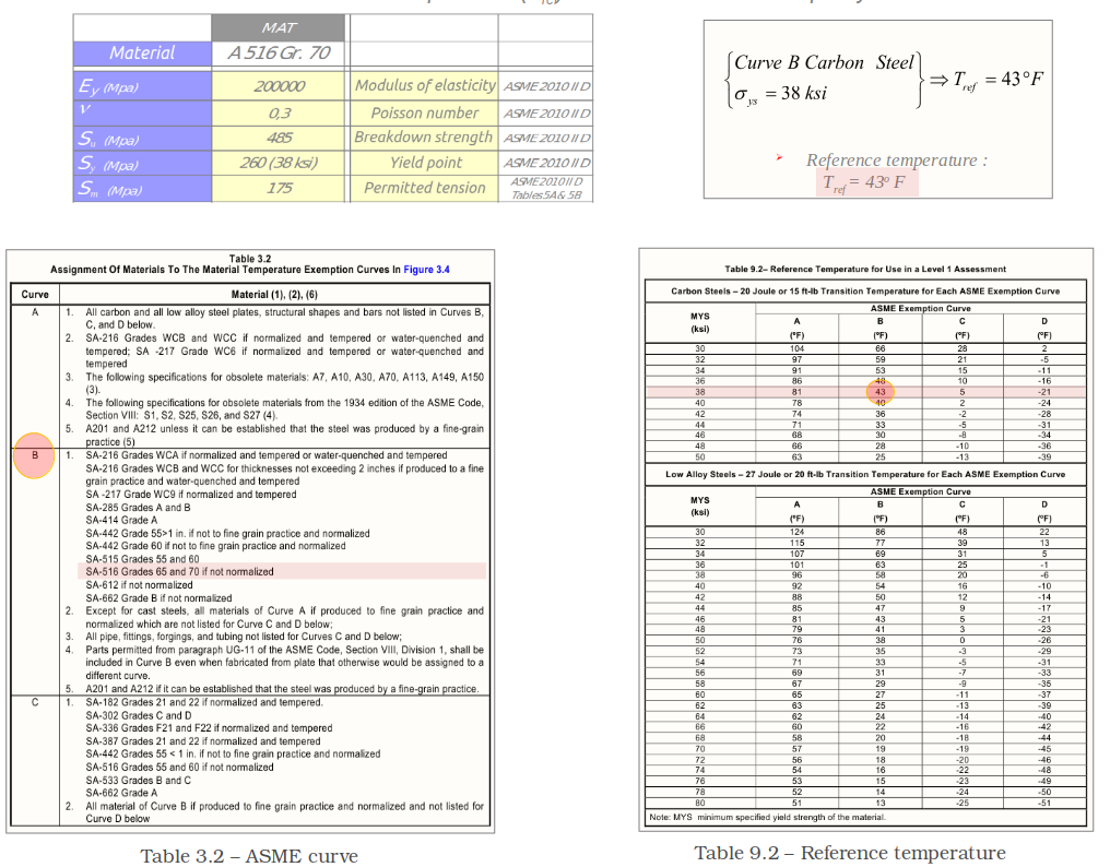
- Determination of reference temperature (Tref) in the case of material quality SA-516 Gr. 70
Step 6
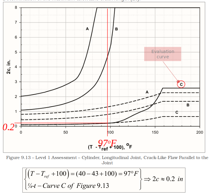
- Determination of the maximum allowable crack length (2c).
Step 7
- Evaluation
